The Geometry Factor
Patrick De Vos, Seco’s Global STEP Manager (Seco Technical Education Programme) discusses the role that cutting edge geometries play in the machining process.
When trying to assess the value of an insert, there are several things to be aware of during the process.
Firstly, the properties of an insert are determined by the carbide grade and that grade has to be selected by the user in relation to the workpiece material. The common denominator between the two is the cutting speed. Cutting speed and carbide grade are two parameters that should be chosen to work well together.
Secondly, the properties of an insert are also heavily dependent on its geometry, and the geometry of the insert has to be selected according to the type of operation to be performed; i.e. a roughing or finishing operation. The common denominators here are the geometric cutting conditions (the feed and the depth of cut).
In this article, I want to address the geometries of cutting edges and how to correctly link the geometry to depth of cut, feed and type of operation to be performed.
GEOMETRY TYPES
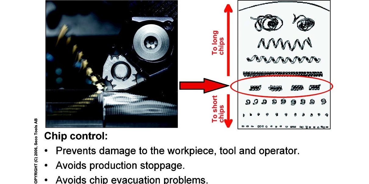
There are two basic types of ‘sintered-in’ insert geometries. The first is called a micro geometry or a micro sharp geometry and is very close to the cutting edge itself. The moment the chip is formed, it is bent, broken and removed by this geometry. These typical ‘F’ geometries produce short chips. The mechanical strength of such a cutting edge is rather limited – everything is concentrated on the cutting edge, increasing fragility. This requires that we limit depth of cut and feed with this type of geometry.
The other basic type of geometry is called a roughing geometry or ‘R’ geometry. The big advantage with a roughing geometry is that it makes the cutting edge stronger; a disadvantage is that we give the chip more liberty, producing longer chips.
The most interesting geometries are combinations of ‘F’ and ‘R’ geometries. At Seco, we call these combined geometries ‘M types’ e.g. the MF5 geometry. With these types of geometries we try to find the best possible combination of mechanical strength and good chip breaking capabilities.
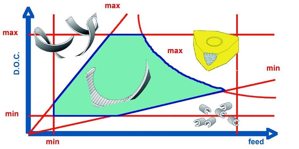
 Whatever geometry we are presented with, we can always make it work, as long as we respect some basic rules about cutting conditions, namely depth of cut and feed. A basic rule for depth of cut is that it should never be smaller than the nose radius of the insert. For ininstance, if you have a radius of 0.8 mm, minimum depth of cut should normally be 0.8 mm. However, in finishing operations, we have to accept that there will always be a natural tendency to produce longer chips as we go below this limit.
The selected depth of cut can’t be too high either, because again, we risk mechanically overloading the insert and that will ultimately result in breakage. The basic rule should be that depth
of cut never exceeds ¾ of the useful cutting edge length (for more fragile inserts such as ‘V’ type inserts, we have to reduce that figure even further).
Another thing we have to respect for an insert is the feed rate. Normally the maximum value for the feed rate is half the nose radius of the insert. For instance, if you have an insert with a nose radius of 0.8 mm, we should normally never use a feed which is higher than 0.4 mm.
WIPER INSERTS
There is an increasing demand for so called ‘wiper’ inserts. A wiper point offers the possibility to overcome this feed limit and apply higher feeds (at lower depth of cut) even on an insert with a smaller nose radius. This is important to remember if you are looking for maximum productivity. The feed can’t be too small, because the cutting edge itself won’t cut and the operation is reduced to a rubbing process. With some of the ‘F’ geometries we can go very low in feed because these cutting edges are specially developed to handle very low feed.
Another very important factor is the ratio between depth of cut and feed to achieve well-shaped chips, i.e. chips that are not too long, and not too short. The ratio of depth of cut to feed should also be within certain limits. Based on empirical measurements for long chipping materials, the ratio of depth of cut to feed should be somewhere between five and 15.
Normally, we consider an ideal ratio of depth of cut to feed to be somewhere around 10. For instance, if we have selected a feed of around 0.3 mm, the ideal would be to combine that with a depth of cut of 3 mm.
IDEAL RATIO
All of these considerations, when put together in one picture, are what most of our customers know as the chipbreaking diagram. Depth of cut not too high, not too low; feed not too high, not too low; the ratio of depth of cut and feed should be close to what is ideal for having the correct chip shapes and the product of the two should not be too high because otherwise we risk breaking the insert.
Looking at the chip breaking diagram, you can see directly how to solve chip breaking problems. If you are operating outside of these parameters, problems will occur. Of course there is much more to say about the impact of a geometry on a turning operation. The geometry of a cutting edge is the sum of the cutting edge geometry itself, the chip breaking geometry and nose geometry.
Correct selection of the best combination of geometries offers many possibilities for further optimising the choice. If a customer wants to go one step further and wants just a few technically
optimized inserts, this is also possible using, for example, the MF5 geometry.

All practical limits together form the "chip breaking" area of an insert.
At the cutting point, we see an ‘MF’ geometry which behaves as a rather sharp geometry; the cutting forces and parameters related to those cutting forces are relatively low with this type of insert. This sharp cutting edge is combined with a geometry we could call a type of ‘R’ geometry, just a few tenths of a millimeter from the cutting edge. It’s a geometry that offers the chip some space to be shaped in a smooth way, further reducing cutting forces on the cutting edge.
An MF5 geometry is, in this respect, mechanically rather strong and gives us more certainty in the selection of depth of cut and feed, resulting in smaller cutting forces. This is a very interesting situation in turning because we have also further reduced the risk of vibration, we don’t need so much power to make the insert work and we don’t have too much risk of bending either the workpiece or cutting tool. If we look towards the point of the insert we can see two small bumps that provide chip control by restricting its liberty away from the edge.
Those two bumps on the face of the insert give us a somewhat hidden advantage; combined with coolant pressure they push towards the point of the insert, creating a kind of a “pressure chamber”. We can see that the coolant is going to enter the pressure chamber, create extra pressure on the bottom side of the chip and push it up much further. This pressure encourages the chip to break.
It’s the first time we see this type of geometry and this offers, of course, very big advantages for optimized machining. The risk for having overly long chips is strongly reduced by using this geometry. In MF5 we have a cutting geometry which, if correctly used, is “custom” made for modern thinking in metal working.

