The role of average chip thickness in milling operations
Patrick de Vos is Seco’s Global STEP manager (Seco Technical Education Programme). Patrick discusses here the role of average chip thickness in milling operations.
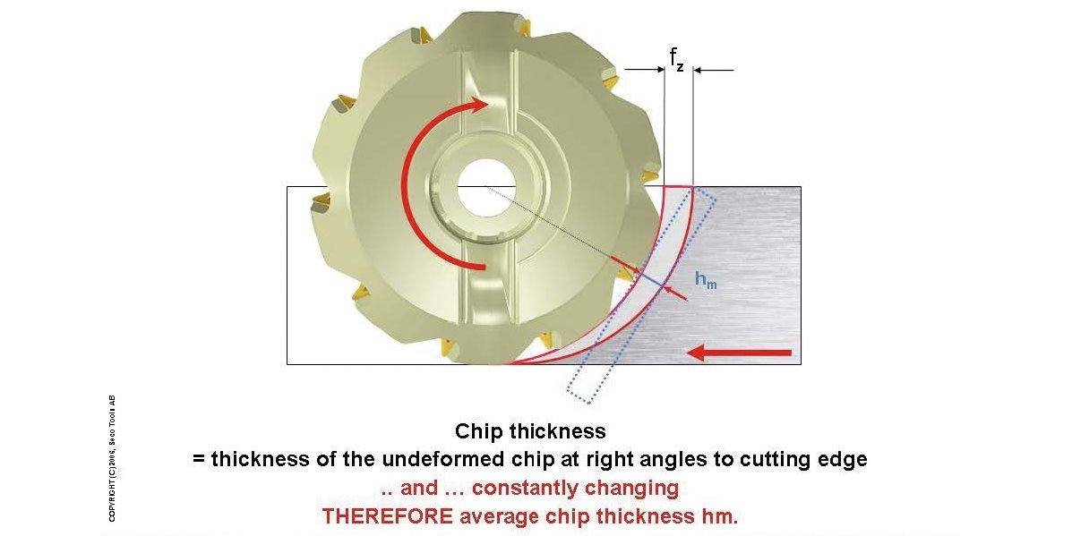
The term “chip thickness” comes from the theory of general machining. It is the thickness (measured perpendicularly to the cutting edge) of the material to be machined. The following relationship exists between the feed and the chip thickness: h = f x sin Kr. whereby his the chip thickness, f the feed and Kr the entering angle. With turning tools, the entering angle is usually
93° or 95°. Feed and chip thicknessare then virtually the same.
With milling, the chip thickness is determined in the same way. Because milling is a ‘two-dimensional’ operation the basic concept must be applied correctly. In a typical milling operation, the thickness of the material located just in front of the cutting edge changes constantly. The result of this is that with a certain feed the chip thickness changes accordingly. That is why the term ‘average chip thickness’ was introduced: the thickness of a “theoretical” rectangular chip with the same surface area and length as the actual chip.
SECOND DIMENSION
With milling, a relationship between the average chip thickness, the milling method, the feed per tooth and the entering angle can be defined. In this case, the ‘second dimension’ needs to be taken into account during the operation. This is achieved by applying the ae/Dc ratio, whereby Dc is the diameter of the cutter and ae is the radial cutting depth during the operation.
Why is the average chip thickness so important? All research into the behaviour and possibilities of the different cutting edge geometries are largely based on the used (or desired) average chip thickness. All sorts of factors, such as cutting temperature, cutting forces, chip formation and removal, tool life, cutting edge wear and vibrations are strongly affected by the relationship between the cutting edge geometry and the average chip thickness. If the milling operator works with the same cutting conditions as the designer of the cutting edge, he is able to optimize and predict the cutting behaviour. And because the same average chip thickness with different operations results in different feeds per tooth, he is able to maximize the operation’s productivity.
THE TOOLS
Which practical tools are available? First of all, the ISO-name of the insert. In code position 10 the options with regard to the geometric cutting conditions (cutting depth and feed) are given. Seco uses a code for this in which the letter represents the degree of difficulty of the operation and the number represents the average chip thickness under normal operating conditions in traditional workpiece materials. For example, M14 means: operation under normal circumstances with an average chip thickness of 0.14 mm in standard steel or stainless steel. Another tool is the cutting edge graph, in which the degree of difficulty of the operation is marked off on the vertical axis and the correct chip thickness on the horizontal axis. With this graph it is possible both to select a specific cutting edge geometry and to solve problems during the operation. After assessing the degree of difficulty, the right cutting edge geometry and corresponding average
chip thickness can be determined.
FEED PER TOOTH
The ISO code and the cutting edge graph help to determine which average chip thickness should be used for a specific cutting edge in a specific operation. It is important to convert this value into a feed per tooth (table feed). There are several practical tools for this. Conversion charts can be used that list the applied feeds for a number of ae/Dc ratios and a number of average chip thicknesses. Also useful is a conversion graph. This shows the influencing factors when determining the feed for a desired average chip thickness by means of correction factors.
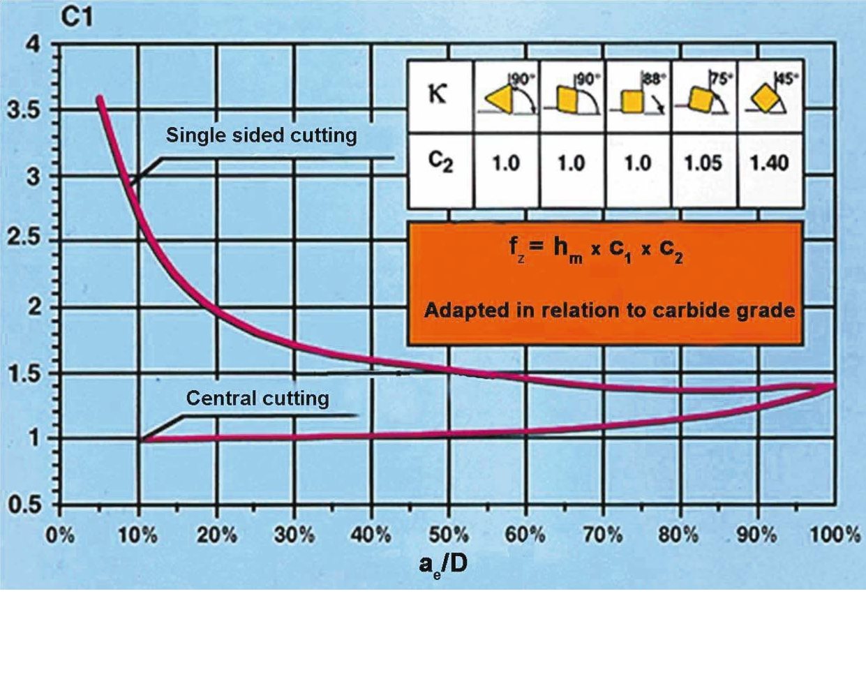
The cutting method is taken into account (off center or central milling), the ae/Dc ratio and the entering angle (and indirectly the strength of the cutting edge used) of the cutter. Based on two correction factors it is determined which feed per tooth is suitable for a specific average chip thickness. Correction factor C1 takes into account the ae/Dc ratio during the operation and the cutting method used. Correction factor C2 considers the entering angle of the cutter. A number of safety factors have been included in the graph to ensure that the maximum chip thickness, that is to be cut by the cutting edge at a certain moment, is not exceeded.
EXAMPLE
A 100 mm cutter with an entering angle of 90° is used for face milling of a surface of 20 mm wide. The milling method used is central milling. The average chip thickness is known (see code position 10 in the name of the insert): 0.14 mm. In the chart we see that for an ae/Dc ratio of 20/100 (=20%) C1 has a value of 1; for an entering angle of 90°, C2 also equals 1. This means that the feed to be used equals 0.14 x 1 x 1 = 0.14 mm/tooth. If the user decides to carry out the operation with a 45° cutter the feed will be 0.14 x 1 x 1.4 = 0.20 mm/tooth. Using the off center milling method the feed would be 0.14 x 2 x 1.4 = 0.40 mm/tooth. This means an increase of the initial feed rate by 186% with the same average chip thickness, or in other words, with the same cutting edge load, cutting temperature and tool life.
CONCLUSION
In order to optimize the use of milling tools one needs to know the right average chip thickness and be able to convert it in a practical manner into the right cutting conditions, in this case the feed per tooth. The tools described above are essential for this. The term average chip thickness and the different ways it can be used to increase the productivity of milling operations are discussed in great detail during the STEP training programme organized by Seco Tools.
The average chip thickness is the most important cutting condition for milling tools that are used in, for example, difficult materials (hard milling) or in specific technological approaches, such as high-speed milling.