Make Milling Dynamic for Shorter Cycle Times and Longer Tool Life
Dynamic Milling not only shortens milling cycle times by 40% to 70%, it often doubles or triples tool life while improving workpiece surface finishes. Additionally, the milling strategy boosts material removal rates (MRR) and helps control heat generation. All of which ensures process security, especially when it comes to unmanned operations.While Dynamic Milling has been around for quite some time, many shops still neglect this productive metal cutting strategy, either because they don’t know how to implement it or don't understand how it works. Instead, these shops tend to run their machine tools as fast as possible, while others stick with outdated speed and feed parameters that fail to produce optimal results.
Dynamic Milling not only shortens milling cycle times by 40% to 70%, it often doubles or triples tool life while improving workpiece surface finishes. Additionally, the milling strategy boosts material removal rates (MRR) and helps control heat generation. All of which ensures process security, especially when it comes to unmanned operations.
In conventional roughing, the goal is to remove as much material in one pass as possible, and to reach true roughing optimization, shops must opt for speeds and feeds that their machine tools and software can sustain throughout each milling path. Using 4 or 5-flute endmills and standard pocketing routines, these shops will engage 50% to 100% of the tool, but unfortunately with this practice, problems arise when the tool enters a corner. Because the tool stepover is not adjusted accordingly, the cutter basically becomes too engaged which causes it to chatter. This chatter, in turn, transfers to the part surface and causes premature tool wear as well as poor surface finishes requiring extensive secondary operations.
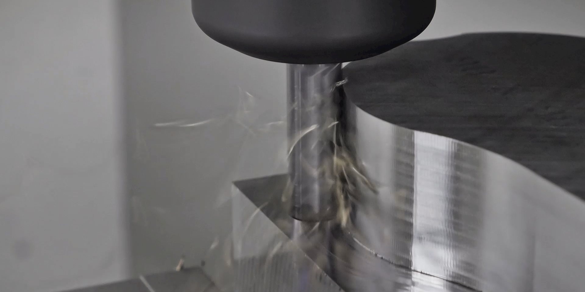
Dynamic Milling, on the other hand, hinges on maintaining a constant angle of engagement (AOE) or arc of contact (AOC) with the tool. Changes in an end mill's AOC with a workpiece affect the tool, workpiece itself and the machine tool. To extend tool life and produce better parts, Dynamic Milling ensures a consistent AOC between end mill and workpiece, along with sustainable speeds and feeds.

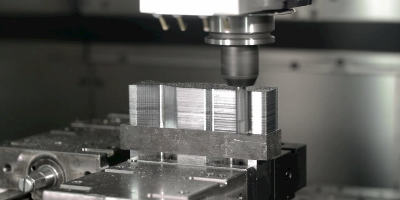
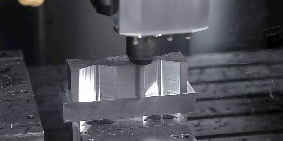
The strategy uses solid carbide multi-flute end mills with a cutting path program that involves large depths of cuts – often the full length of the flute – and shallower radial stepovers while maintaining a constant AOC. Greater AOCs increase the load on the tool as well as the machine and generate more friction and heat, which compromises tool life and surface finish.
Dynamic Milling is ideal for machining outside profiles and pockets on 2D prismatic type parts such as those often found in the aerospace manufacturing and general engineering sectors. It is also effective for other part features that allow for using the whole flute length of the cutter at a 3 to 4xD, and in some instances 5xD, axial engagement. With its shallow stepovers and high depths of cut, Dynamic Milling makes it possible to machine parts three to four times faster while also significantly reducing tool wear, therefore, increasing tool life.
Its shallow stepovers, however, prevent the use of Dynamic Milling for complex 3-D contours and surface features. These types of parts may still be faster to rough out with Dynamic Milling in theory, but shops must consider the downstream effects. The strategy will produce 3-D surfaces with big stair steps left behind by the large depth of cuts, so even if it’s significantly faster than using another milling strategy, it will require additional semi-finishing passes to achieve a near-net shape.
Discover your free guide to Dynamic Milling
All the variables of Dynamic Milling – machine, CAM software, cutter and tool holder – have an impact on the success of the process and on the tool’s performance. On the machine tool side, high acceleration/deceleration capabilities are needed for Dynamic Milling. They must also have controls with advanced lookahead (a couple thousand lines) functionality, glass scales and good overall rigidity to keep up with the relatively complex cutter paths involved with Dynamic Milling.
In some instances, feedrates during the strategy can run as fast as 8,300 mm/min (325ipm), in P2 steel. To accommodate those speeds, machines need newer linear drive technology, and for some applications full simultaneous five-axis movement is also a plus. Additionally, machines must have high torque and high rpm capabilities because of the reduction in cutter stepover. In Dynamic Milling, it is not uncommon to run a machine spindle at 10,000 or 15,000 rpm, depending on part material, and at feedrates of 700 or 800 ipm. Plus, the machine spindle has to be able to handle heavy radial side pressure, so DIN (equivalent CAT) spindles with taper-face connections or HSK style spindles are often recommended.

When tooling up for Dynamic Milling, shops must carefully consider tool diameters and flute counts. Typical tool diameters used are 12mm to 20mm (0.250” to 0.750”). A good rule of thumb is that tool diameter should measure a third or fourth of the cutting length/depth of cut and the tool must have chip splitters for good chip formation, especially while machining a closed pocket.
Tool design relies on the combination of geometry, material and coatings. For enhanced tool life and performance, modern cutting tools use physical vapor deposition (PVD) coatings applied through the process of sublimation, in which materials pass directly from solid to gas with no intervening liquefaction. These coatings often consist of a combination of titanium and nitrogen with aluminum, silicon or other elements such as silicon.
Cutting tool flute count is where many shops struggle. What they need to realize is that, in Dynamic Milling, the percentage of stepover has to be adjusted according to the endmill’s number of flutes. The more flutes, the less the stepover percentage, mainly because of chiproom.
Dynamic Milling generates massive amounts of long thin chips, and the more flutes a cutter has, the smaller/narrower its chip evacuation gullets. Using the strategy in pockets further magnifies the need for efficient chip evacuation. It is for this reason that Seco developed its chip splitters, specifically designed for dynamic machining. These chip splitters can be utilized for both dynamic roughing and finishing.
On a tool diameter of 10mm with a 40mm flute length (inch diameter 3/8" with a 1½" flute length) for instance, Seco imparts three special chip splitter grooves – with radial reliefs and axial clearance – on each flute, but these grooves are never in line with or overlap each other. The resulting shorter chips do not build up in the cutter flutes and are more easily evacuated through a machine’s air blast and standard chip conveyor.
It is often said that the best tool can be destroyed by the worst program, so the right CAM software is critical to Dynamic Milling. Fortunately, current CAM software often includes dynamic packages for such milling strategies to handle program generation and the large amount of code needed for movement on complex spindle/cut paths.
Current software strategies rely on two basic approaches to Dynamic Milling toolpaths. One applies a constant feedrate and AOC to concave or convex part features and achieves maximum metal removal rates with varied stepovers between passes. The second approach varies feedrate and AOC but maintains a constant stepover to produce consistent chip thickness. In this approach, the tool's AOC can reach between 80 degrees and 140 degrees, depending on the CAM software. That high angle of engagement forms the opposite of the Dynamic Milling approach.
In operation, CAM software packages monitor tool engagement and will slow feedrate in corners or areas where designated width of cut causes greater AOC than in straight cuts. To accomplish this, CAM software suppliers have developed refined path algorithms that control tool engagement in real time for highly productive, reliable machining of simple and complex contours.

The most commonly overlooked aspect of machining strategies, including Dynamic Milling, is tool holding. In general, for solid milling tools, the holder should provide good transmittable torque and less than 10micron (inch 0.0004”) runout. Any level higher than that cuts tool life in half.
The reason low runout is critical is because the high speeds and feeds of Dynamic Milling tend to magnify any amount of runout. Besides that, the forces of Dynamic Milling can cause cutters to pull out of toolholders, especially when larger diameter tools are used. In light of that, any cutter diameter 12mm (inch ½") and above should be run in a milling chuck or a holder with high transmittable torque. Plus the mass of the larger holders will help dampen vibrations. Under 12mm (inch ½"), common holders such as shrinkfit are acceptable. Don’t overlook high precision collet chucks that offer versatility with minimal runout and great transmittable torque.
Dynamic Milling offers highly effective results on applicable parts and features. The strategy can make a dramatic improvement in part cycle times, surface finishes, tool life and machine tool usage. Shops that take the time to understand Dynamic Milling can improve their productivity, efficiency and profitability on parts that make good candidates for this strategy.
To achieve the best possible results, shops should take advantage of cutting-tool supplier expertise to fine tune their approach to individual jobs. Shops don’t have to travel the Dynamic Milling path alone, and Seco is there with support every step of the way. While this and other strategies can be intimidating, Seco and their applications engineers make the learning curve smaller and implementation smoother.
Inline Content - Survey
Current code - 5fce8e61489f3034e74adc64