Passive/Dynamic Vibration Control Technology Boosts Metalcutting Productivity
Uncontrolled vibration creates multiple problems in metalcutting operations.Fagersta, July 2017 - Uncontrolled vibration creates multiple problems in metalcutting operations. Varying forces in the cutting process cause vibration and tool chatter that degrade part surface quality, quickly wear or break cutting tools and damage machine tool components. Trends in product design can also incite vibration. To enhance product strength and reduce assembly costs, manufacturers increasingly machine parts from monolithic workpieces. Producing internal features of the parts requires tools to reach into deep cavities, and the extended tool length exaggerates vibration. Attempting to minimize vibration by reducing cutting parameters decreases productivity and increases manufacturing cost.
Prime among the various approaches to vibration control are passive/dynamic systems that utilize tuned-mass damper concepts to absorb vibration before it progresses and disrupts the machining process.
Vibration is a Common Issue
All sectors of industry recognize excessive vibration as a destructive condition. Repetitive operating and/or external forces generate sympathetic motion that can resonate within a machine, building, or bridge and grow to a dangerous magnitude. Manufacturers and builders often apply tuned mass damper concepts to overcome vibration. A tuned mass damper is a component that is suspended within a machine or structure and is designed to resonate out of phase with the unwanted vibration, absorb its energy, and minimize the vibratory motion.
Vibration in Metalcutting
In metalcutting, vibration is generated by the changing forces that occur when making chips. The intermittent forces are apparent in the interrupted cutting process of milling and also appear in turning operations when the toolholder bar is periodically loaded and unloaded as chips form and break.
A passive approach to vibration control in metalcutting involves maximizing the rigidity of the elements of the machining system. To restrict unwanted movement, a machine tool can be built with rigid structural elements, made larger and heavier, and filled with concrete or other vibration-absorbing material. From a workpiece perspective, thin-walled parts and those with unsupported sections are prone to vibration when machined. To a limited degree, parts can be redesigned to improve rigidity. However, such design changes can add weight and compromise product performance.
For cutting tools, a passive approach to vibration control includes use of short, rigid tools and replacement of steel toolholders with those made of stiff tungsten carbide.
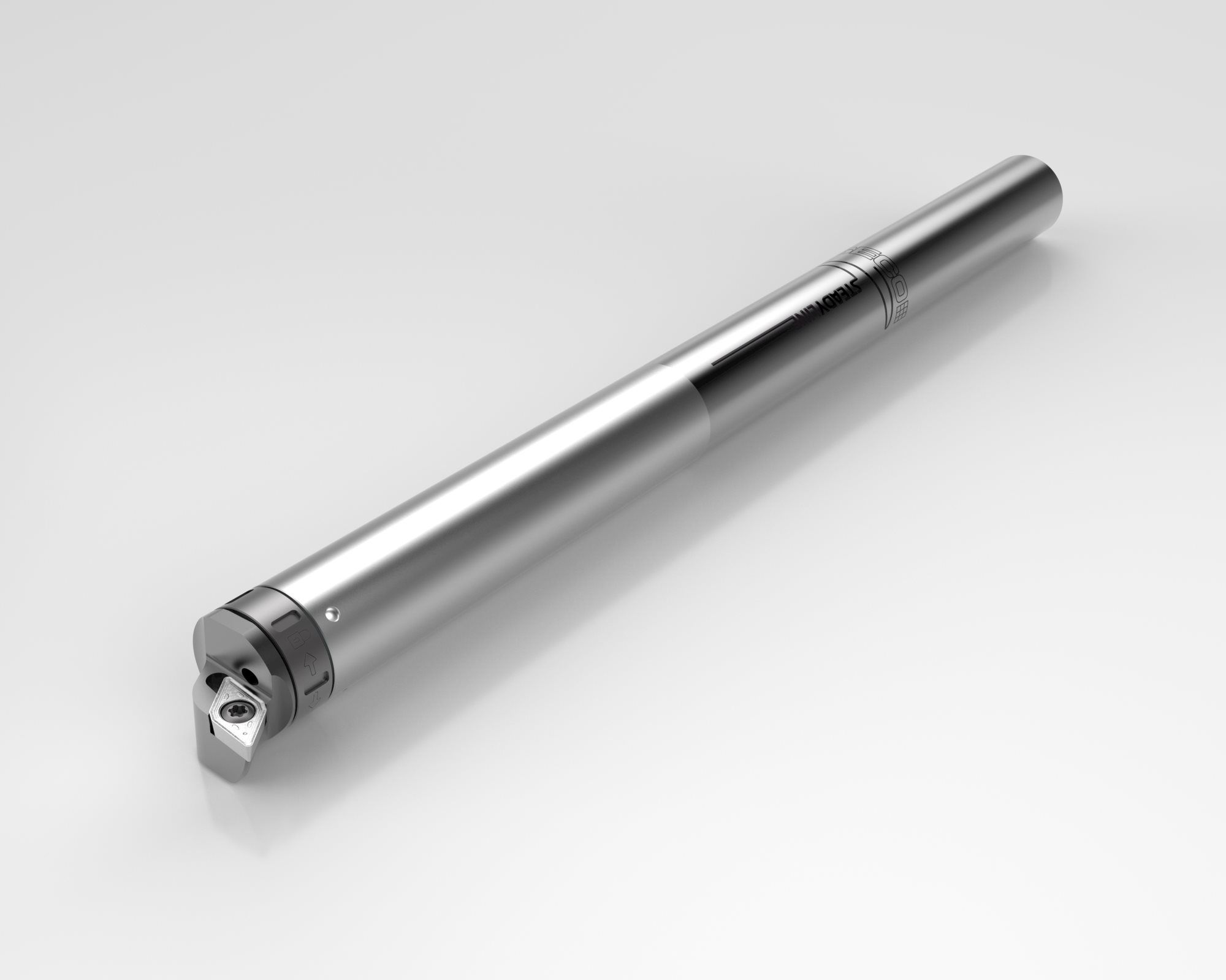
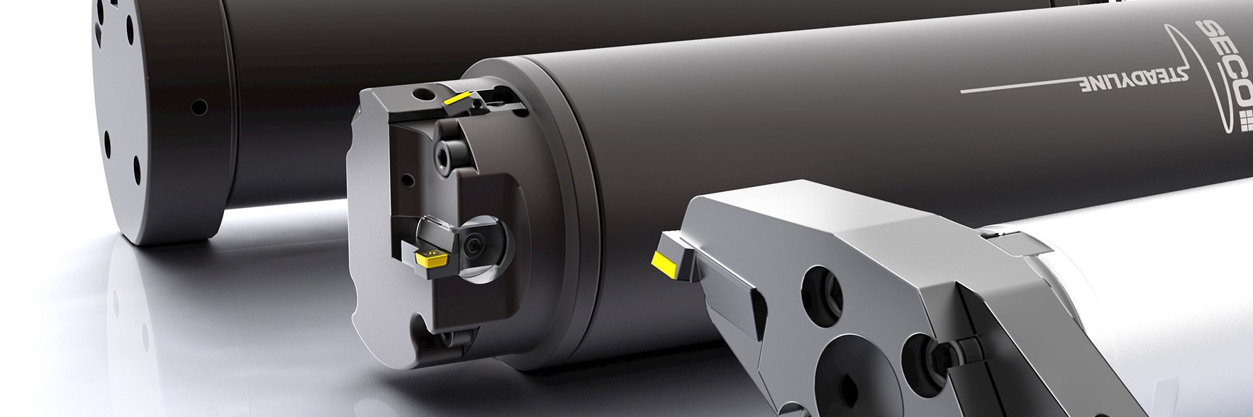
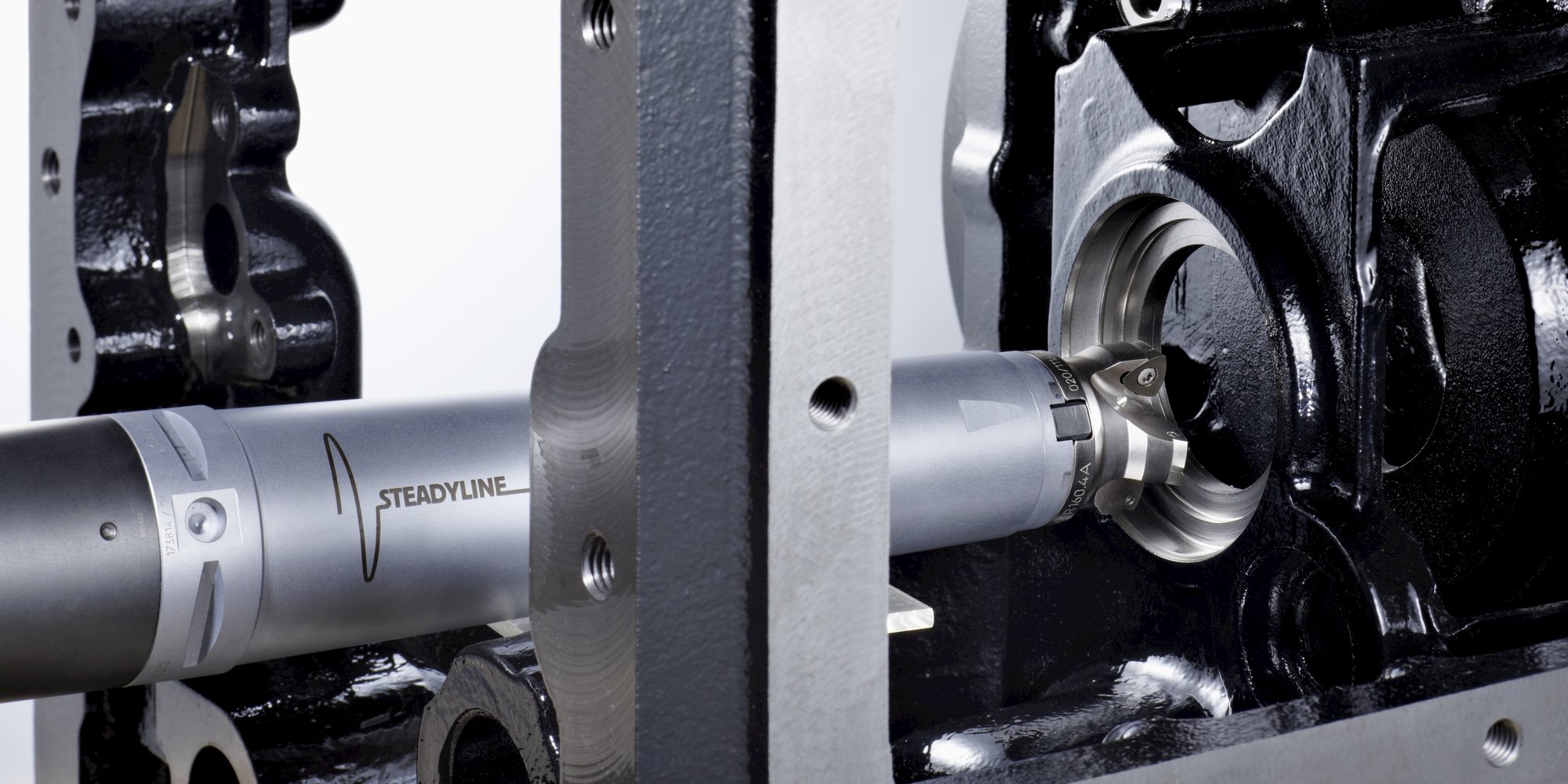
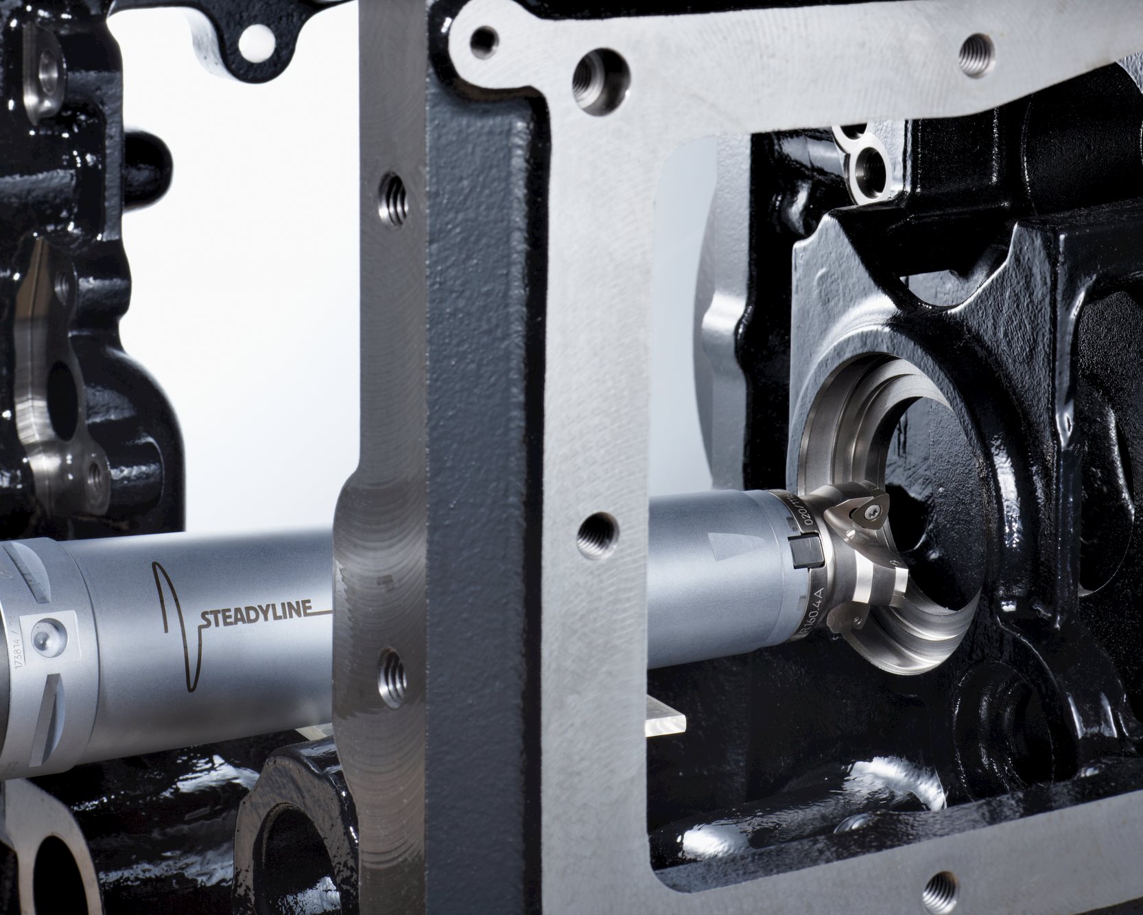
A passive/dynamic approach to vibration control for tools involves application of the tuned mass damper concept. The Steadyline system from Seco features a pre-tuned vibration damper consisting of a damper mass made of high-density material (to minimize its overall dimensions) suspended inside the toolholder bar via radial absorbing elements. The damper mass absorbs vibration immediately when it is transmitted by the cutting tool to the body of the bar.
The Steadyline system can enable typical long-overhang operations to be performed at least twice as fast as with non-damped tools while enhancing part surface finish, extending tool life, and reducing stress on the machine tool. Passive/dynamic vibration damping technology can make it possible to accomplish certain applications, such as some uses of tool lengths of up to 10 times bar diameter, that would not otherwise be possible even at minimal machining parameters.
Passive/Dynamic Operating Principles
Implementation of the Steadyline system adds the properties of a second MKK’ system, namely mass M2, rigidity K12, and density K’12. MKK’ system S2 is engineered to possess the same natural frequency as the original MKK’ system and resonate out of phase with the unwanted vibration, thereby absorbing its energy and damping the vibrating motion.
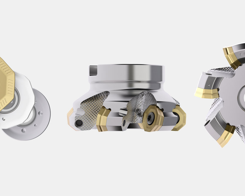
In the Steadyline system the vibration-absorbing mass is positioned at the front of the bar, where potential for deflection is highest and the mass can damp vibration immediately when it is transmitted from the cutting edge to the body of the bar. The Steadyline system also includes short, compact GL cutting tool heads that place the cutting edge close to the damping mass to maximize the vibration-absorption effect. The system is adaptable to a wide range of applications and is most useful in milling (contouring, pocketing and slotting), turning and both rough and fine boring operations.
Application Comparisons
A good example of the Steadyline system’s effectiveness involved a difficult boring operation in 42CrMo4 steel where a cylindrical 105.8 mm bore was enlarged to a conical 129 mm bore in five roughing passes at a 3 mm depth of cut decreasing to 0 mm depth. With an 80 mm dia. bar, the initial cutting length was 600 mm, representing an extended tool length-to-diameter ratio of 7.5. Roughing was accomplished at a feed rate of 0.3 mm/rev and cutting speed of 157 m/min. Pre-finishing to a final 130 mm diameter took place at 0.5 mm depth of cut, 0.2 mm/rev feed rate, and a cutting speed of 200 m/min. Even though the bulk of the workpiece prevented use of the full rotational speed capability of the Steadyline bar, machining time in the operation was reduced from 12 hours to 2 hours (more than 80 percent) with use of the Steadyline passive/dynamic vibration-control system.
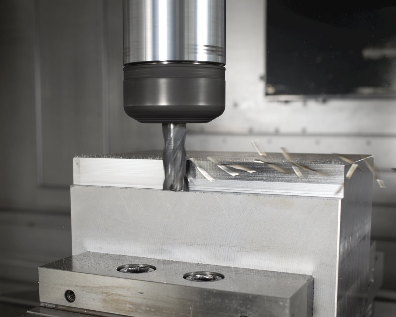
Demonstrating the Steadyline system’s benefits in a side milling operation, a Combimaster milling cutter holder without passive/dynamic vibration control was applied with a 20 mm diameter cutter at 312 m/min and 0.3 mm/tooth feed rate at a cutting depth of 0.9 mm in 1.1206 CK50 steel. When a version of the same tool employing the Steadyline system was applied at the same cutting speed and feed as the undamped version, it was possible to increase cutting depth to 2.2 mm (an increase of 2.3 times) without unwanted vibration.
Conclusion
Producers of equipment for oil and gas, power generation and aerospace customer are prime candidates for use of passive/dynamic vibration control systems because each of these industry segments regularly deals with large, complex parts with features that require the use of extended-length tools. Additionally, such parts usually are made from tough alloys that are difficult to machine and thereby produce high, vibration-generating cutting forces. However, it is clear that nearly every manufacturer faces applications where the vibration-absorbing properties of Steadyline tooling can expand their capabilities, improve their productivity and reduce their costs.
(Sidebar)
Steadyline Hardware, Mounting, and Application Considerations
Hardware Details
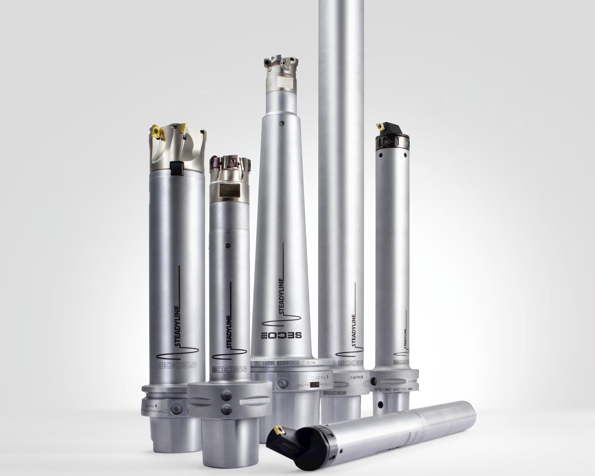
The Steadyline passive/dynamic vibration control system includes a comprehensive selection of hardware for milling, turning and boring applications that can be assembled to meet widely varying manufacturing requirements.
The turning tool system can be used for turning and boring and includes 7 shank diameters, including 32 mm, 40 mm, 50 mm, 60 mm and 80 mm, as well as 2.5" and 3.0" sizes. Three tool lengths – 6xD, 8xD, and 10xD – are available for each diameter with a variety of machine-side connections. These include cylindrical shanks for 32 mm to 80 mm metric and 1.25" to 3" imperial, as well as Seco-Capto and HSK-T/A.
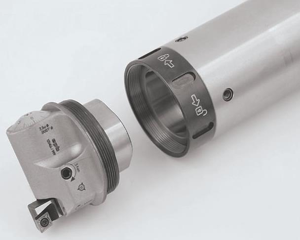
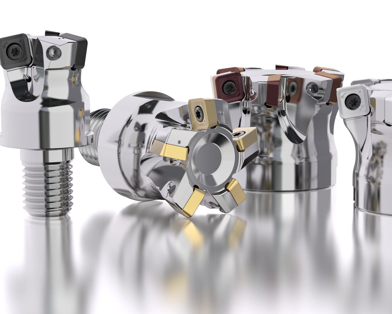
Bars with diameters of 50 mm or less directly accept compact GL cutting tool heads with accurate polylobe-based connections that are secured via a fast and convenient nut system.
Bars with diameters of 60 mm or larger feature BA connections that are locked by four Graflex screws and allow 0˚/180˚ positioning. These larger bars can be used for turning with BA-to-GL adapters and compact GL50 cutting tool heads, as well as for boring with BA boring heads available as custom tooling.
GL heads exist for rough and fine boring applications, as well as for turning applications with right-hand and left-hand cutting versions. Negative inserts are offered for roughing and positive inserts for finishing, as are inserts for threading, grooving and parting-off.
In addition to a wide selection of standard tools, Seco also provides custom problem-solving solutions such as bars with multiple cutting edges and very long bars (more than two meters) for special applications.
For milling, Steadyline vibration-control configurations are available with Combimaster replaceable head milling cutters for diameters from 20 mm to 40 mm and shell-mill holders for cutters from 40 mm to 160 mm in diameter. Both the Combimaster and shell-mill versions are suited for square shoulder, copy, end, face, plunge and disc milling with many insert styles, as well as contouring and helical interpolation ramping. The tool bodies’ conical-reinforced cylindrical shapes achieve high static and dynamic stability in heavy milling applications. Seco-Capto, HSK-A, BT, CAT and DIN (including a taper face version) machine-side connections are available for milling holders.
Custom tooling for milling applications can also include special components such as Shrinkfit clamping and special collets.
Tool Mounting Guidelines
Steadyline tools are essentially “plug-and-play:” the built-in damping system is ready to use without further preparation. To achieve best results, the bars must be mounted directly on the machine without intermediary extensions or reductions. When mounting the tools on a machine, the Seco-Capto system is recommended due to its rigid, simultaneous face and taper contact and high bending resistance that maximize accurate positioning of the cutting edge. When Seco-Capto is not an option, cylindrical bars should be clamped in a split boring bar holder and inserted to 4xD, which is marked by the second line on the bar.
Application Tips
Special application considerations exist for Steadyline tooling. When directly replacing a conventional bar with a passive/dynamic Steadyline unit, it may be necessary to increase cutting conditions to generate vibrations sufficient to fully trigger the system’s damping response. In addition, at long overhangs the bar may bend but not vibrate and create a smaller diameter than programmed. Breaking the operation up into three lighter cuts should eliminate the bending and produce the programmed diameter. It is essential to note that the minimum machining diameter must be large enough relative to the bar diameter to allow for correct evacuation of chips. Taking chip evacuation into account is vital, especially in small and deep holes. The use of coolant is recommended to aid with chip evacuation and minimize heat transference to the bar, which is temperature sensitive.
This article can be downloaded under http://gallery.secotools.data-room.de/download/20269.pdf