Understanding Tool Wear
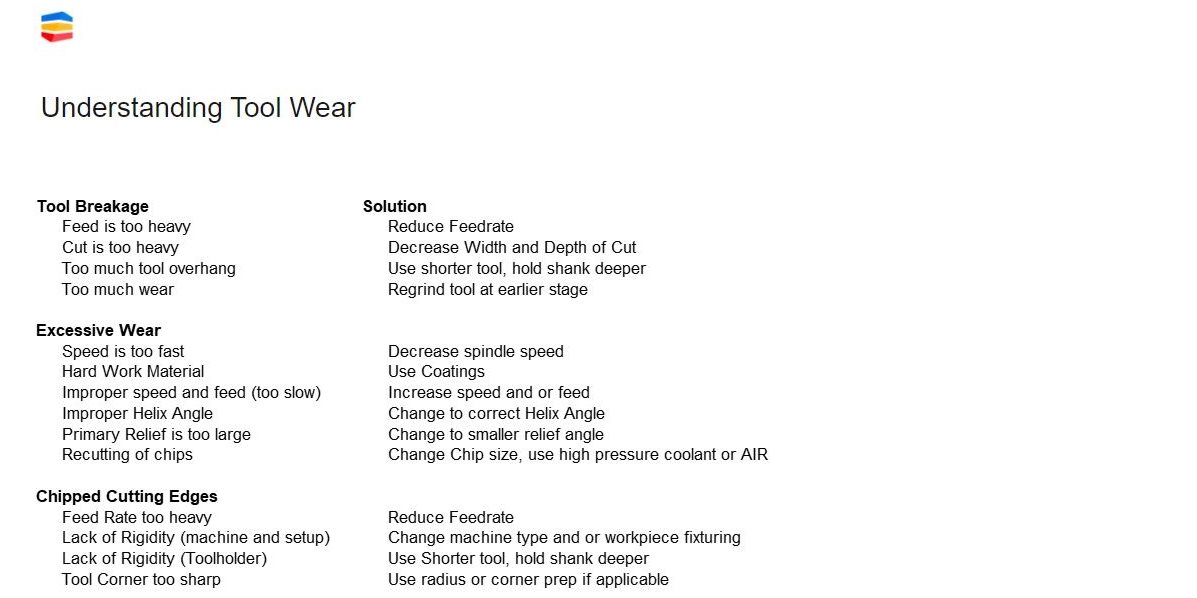
Recognizing and understanding the factors affecting tool wear and tool failure are crucial to efficient, cost-effective machining. Tool failure and tool breakage are the leading issues in the industry, and factors affecting tool wear include improper speeds and feeds, poor chip evacuation resulting in recutting of chips, improper helix angle and hard workpiece materials.Time is money. And so is tool wear. Tool wear and tool failure cost shops money in terms of tool replacement, lost production due to downtime for repairs and tool changeovers, additional secondary processes and scrapped parts. Excessive tool wear and tool failure makes for unsustainable manufacturing. Understanding the factors affecting tool wear and how to measure tool wear are crucial to achieving efficient and cost-effective machining.
There is an entire shop full of tool wear types, and successful machining depends on accurate troubleshooting and understanding the role machining parameters play in tool life longevity.
Generally, factors causing excessive tool wear include improper speeds and feeds, poor chip evacuation resulting in recutting of chips, improper helix angle and hard workpiece materials. Decreasing spindle speeds to match lower feed rates, using appropriate tool coatings and grades for the work material at hand, choosing the correct helix and relief angles and applying high-pressure coolants can all play a part in reducing tool wear, thereby, extending tool life.
Common tool wear conditions include flank wear, crater wear and chipped cutting edges.
Tool wear, of course, is inescapable, and of all the possibilities, flank wear – a relatively uniform abrasion along the cutting edge – is the most desirable form of tool wear. It is predictable and dependable, so measures can be taken to avoid disaster with adequate tool wear monitoring. Erosion is the primary cause of flank wear as are low cutting speeds. On the other hand, higher temperatures generated by high cutting speeds will create the right conditions for diffusion to occur, which also contributes to flank wear. Optimizing cutting speeds, using harder carbide grades and the correct coolant application will mitigate against flank wear.
Crater wear is a common cause of premature insert wear. Heat causes tungsten carbide grains in the substrate to decompose and leech into the chips. This wears a crater into the insert’s rake face. The crater can grow enough to cause the insert flank to chip or cause rapid flank wear. Proper coolant application to control machining temperatures, lower speeds and feeds and the use of a heat-reducing free cutting geometries will minimize crater formation.
Mechanical instability in the machine tool setup and inclusions in the workpiece will create small chips in the cutting edge. Processes that involve several interrupted cuts will also cause stress along the cutting edge that will result in chipping.
Reducing feeds on entrance and exit along with increased cutting speeds, proper machine tool setup to maximize rigidity and minimize deflection and using a stronger cutting geometry and tougher carbide grade will help prevent chipped cutting edges.
In this #SecoTechTalk installment, Seco Product Manager Jay Ball reveals that tool failure and tool breakage are the leading issues in the industry. Solid carbide tools and end mills are not designed to break. So if yours are, you need to consider a holistic approach to examining your machines, tools and processes. Check out Jay’s #SecoTechTalk to learn what you need to do immediately if your tools are breaking. Seco’s Tool Wear Analysis can help, too.

For tips on getting the most from your machining operations, catch more episodes of Jay’s #SecoTechTalk on Seco’s Instagram. You’ll find practical advice that makes your machining more efficient and sustainable. Leave a comment to let him know what you want to hear about next.
Inline Content - Survey
Current code - 5fce8e61489f3034e74adc64

